The dieline, which we have already discussed previously, represents the ‘cutting and folding layout of the flat box composed of cut lines, bleed lines and crease lines’ and is therefore the 2D technical drawing of the packaging. Designing this type of file, as anticipated in the article ‘Structural packaging design: windows and inserts’, requires technical knowledge across multiple fields. Its development is closely linked to the type of material used, the production machinery and the technical and functional requirements it must meet. Any variation in these factors often results in changes to the positioning and structure of the dieline guidelines.
Packly generates dielines completely automatically: simply enter the desired box dimensions and the material thickness. The engineering calculations behind this process are significant and result in professional outputs based on numerous technical and mathematical analyses.
Have you ever wondered why each box dieline has that specific shape? Those cuts or angles? Every detail is intentional and serves a specific function. In this article, we will explain some of the design choices behind the development of the dieline of the tuck end box, including the one generated on Packly.
First of all, it is important to note that each box model (and each of its variants) has a specific dieline determined by its type and structure. However, this dieline is not static: depending on the material used and the dimensions, it may vary to ensure optimal packaging performance.
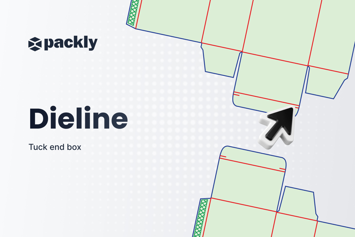
The tuck end box is one of the most common packaging models. Its classic dieline appears as follows:
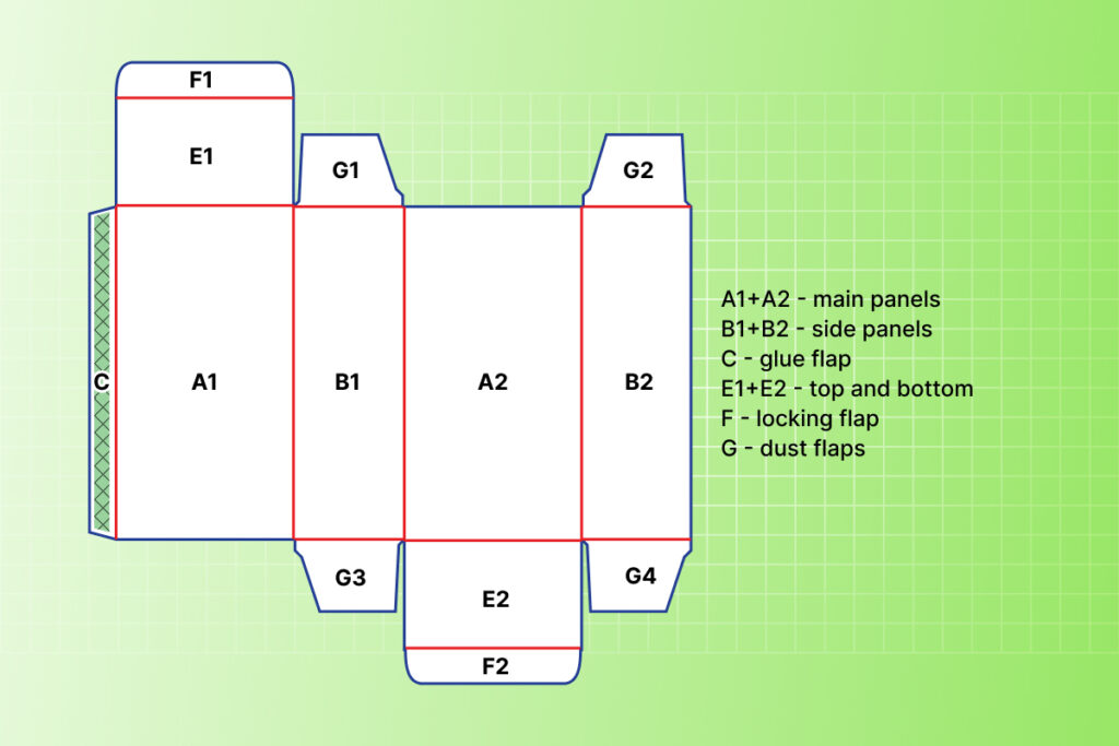
The two panels A1 and A2 represent the main panels of the box, the back and the front; B1 and B2 are the sides of the packaging, while e1 and e2 are respectively the top and the bottom. C is the glue flap and the green texture indicates the area where the glue will be applied, which generally must not contain printed elements. The locking tabs are indicated as f1 and f2, while g indicates the inner flaps of the packaging.
The orientation of the letters placed on the various components of the box is a guideline for the correct placement of the artwork according to standard practices. Of course, depending on your design choices, you are free to position text or symbols as you prefer, even if it means departing from conventions.
As shown in the image, the tuck end box is characterized by a simple tuck closure system on both the top and bottom of the packaging and is glued at a single point.
The various components of the box are sized according to specific structural aspects to ensure proper functionality: the dimensions of the glue flap depend on the overall proportions of the tuck end box, while the size of the right side panel, positioned opposite the glue flap, is determined by the thickness compensation (thickness offset), i.e. a dimensional adjustment required to allow optimal gluing of the packaging. For this reason, B2 will be slightly shorter than B1. An additional thickness offset is also present in panels A1 and A2 to allow the top and bottom flaps to overlap the box walls and inner flaps, ensuring optimal assembly and closure of the packaging.
The closure system may or may not include cuts at the locking tabs, f1 and f2. When present, these create safety locks that secure the flaps and prevent accidental opening of the packaging. This system, both on the top and bottom of the tuck end box, is mainly used for packaging intended for large-scale retail and direct sales. In the cosmetics sector, instead, it is common to combine a safety lock closure on the bottom with a traditional closure (without cuts) on the top to facilitate opening by the customer without compromising the integrity of the packaging. This type of closure is commonly referred to as open/close. The dimensions of the safety locks depend strictly on the size of the box and the thickness of the material used.